Figure1 (click on thumbnails to see full sized)
THE
HAMMARLUND HISTORIAN
SP-600 Re-Capping
This section is provided thru the graciousness of Ray Vasek, W2EC, and is used here with his permission.
A note from Ray:
This is an article I submitted for the Hollow State Newsletter. While there is much info passed around via the internet these days, a good source of written material can still be invaluable. If you are at all interested in the classic vacuum tube radios, I highly recommend a subscription to the Hollow State Newsletter.
For subscription info, contact:
Editor: Barry Hauser
370 Marie Court
East Meadow, NY 11554-4304
Phone: (516) 935-8603 ext. 203
Fax: (516) 753-1797 anytime
E-mail:
or:
Publisher: Ralph Sanserino
PO Box 1831,
Perris, CA 92572-1831
E-mail:
and now,
Recapping the Hammarlund SP-600
by Paul R. "Ray" Vasek - W2EC
w2ec@arrl.net
(changes made to this article in Sept. 2004 include more pictures, and some text additions)
Recently I had the good fortune to obtain a relatively clean SP-600. Although a ham for over forty years, this was my first SP-600 and I was completely unfamiliar with it except for what I’d read in magazines or e-mail reflectors. The problem area mentioned most often was the BBOD, or BlackBeauty of Death.
While waiting for delivery of my radio, I tried to gather whatever information I could in anticipation of a major recapping. While I received lots of good advice and ideas, I didn’t come up with a really concise description of just how many and what kind of caps I should plan on replacing, nor the effort that would be involved. I decided that I would try to keep a detailed log of what I did and the order it which it was done, with the intent of providing some detailed information to help make the recapping process easier for others facing an SP-600 for the first time.
Keep in mind that this is the first, and only, SP-600 I have worked with. I do not pretend to be an expert on them, I am only relating the experiences I have had while working on this one particular radio. Additionally, there are many different models of the SP-600 and there may be various minor differences in the electrical configurations. Some differences may even appear within the same model, for example, my radio is an SP-600 JX-6, and one person who used my data while doing his SP-600 JX-6 was not able to locate a few of the capacitors I identified. So use this as a general guide only and be prepared for things to be a little different than I spell out, especially if your model is not a JX-6. However, a look at the schematics for several different models shows the same basic design to be followed throughout the series. Also, this is not a history of the various SP-600 models or an attempt to define the "best" capacitor to use. I’ll leave that to those who are more familiar with the SP-600.
First off, many may ask, as I did, just what is a BBOD and what goes wrong with them?
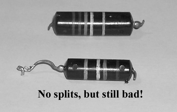
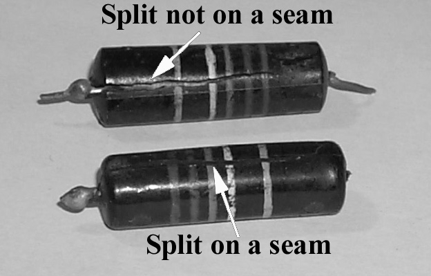
The BBOD is a tubular capacitor, dark gray or black in color with numerous colored bands to identify its value and rating. It looks like a very large old style carbon resistor that might be in the 5 watt class, roughly 3/4" to 1" long and 3/8" to 5/16" in diameter. The name Black Beauty probably comes from the appearance of those caps most often encountered, a body molded of a shiny black material, and the Death moniker comes from the fact that almost every BBOD you encounter will fail, having very poor (high) leakage characteristics. (Later word has it that Black Beauty actually appears to be a real name, a trademark so to speak.) A large number will even have major cracks in them exposing the insides of the capacitor to the air. Some will be almost completely split in half.
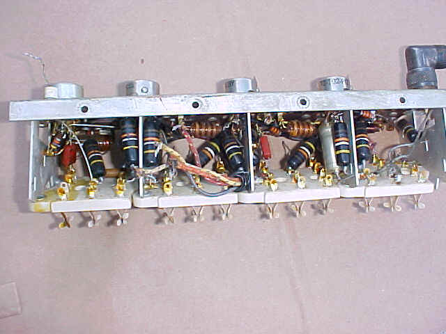
These splits usually occur along the length of the capacitor. Don’t mistake the sealed seam of the capacitor for a split. When you see a split, you’ll know it! Figure 1 shows a pair of capacitors that appear to be in good solid shape with the colored bands plainly seen. Figure 2 shows another pair with splits running the length of the capacitor. While the split capacitors were obviously bad, a test of the "good looking" capacitors showed they were in as poor shape leakage wise as the split caps.
The net is, when it comes to BBODs, just perform a wholesale replacement while you have the radio on the bench.
Figure1 (click on thumbnails to see full sized)
One thing you should be aware of. There are some lucky people out there who will not have to endure the recapping procedure. At some point late in the SP-600 life cycle, at about s/n 17,500, it was apparently recognized that the BBODs were experiencing a high failure rate after years of service. The specifications were then changed and ceramic disk capacitors were used in place of the BBODs. I’ve not seen any reference to similar failures in the ceramic disk equipped SP-600s. So before you start worrying about doing a recapping, check and see if you are one of the few lucky owners of an SP-600 with factory original ceramic disks!
Now that we have decided we should replace all the BBODs, just how many do we need and what types and values are they?
In my JX-6, I found I had thirty-eight BBODs with a value of .01mfd and sixteen BBODs with a value of .022mfd. A check of some later models show a factory change was made to substitute the .022mfd caps with .01mfd caps. This is supported by a military work order authorizing the change, although I can’t reference that MWO number off hand. The consensus is there is no need to get two different values, you can replace all fifty-four caps with .01mfd, although I used both .01 and .022 as called for since I already had them available. There are fifty one caps used for bypass and three used for coupling. In my case I used what I had in my parts bin, .01 or .022 ceramic disks at 1000V for bypass and .01 mylars at 630v for coupling.
Prior to starting the actual recapping, I traced out the schematic locating all the caps as per the parts list.
Then I used the various pictures from the manual to try and locate visually the area where I anticipated the cap should be. I then performed a detailed resistance check of the whole radio based on the manuals resistance chart and found that all values but one were well within 10%, in fact most were within 5%, so I have not yet replaced
any resistors. The one area that was out of spec was the cathode of the 6V6. This was supposed to be 380 ohms but read 1.45 ohms. This turned out to be a failed bathtub cap, a large 10mfd x 100v cap for cathode bypass. I replaced this with a standard 10mfd x 250v cap I had spare. With the new cap the resistance was dead on at 380 ohms. Someday maybe I’ll mount the new cap in the old can so it looks "original". Finally, after a good visual inspection of the radio, I brought power up on the radio slowly (temporarily swapping the rectifier for a solid state rectifier set and using a variac) prior to making any changes at all, in order to be able to make a before and after comparison.Once the radio was fully powered up, I found that it had very weak and distorted audio, capable of picking up only a few of the very strong local AM broadcast stations. The bands above 1.34mc appeared dead. At that point I began to make actual changes to the radio.
From this point on I’ll summarize the steps I went through for the re-capping. I did it by trial and error, particularly the error phase, so maybe this will help get you in the right frame of mind for what might at first glance appear to be a daunting task.
At the end of the article is a list of caps along with a description of where it is located. This location is often identified as being at the "cold" end of a component. "Cold" refers to the connection point closest to ground. I've also indicated whether the cap at that position is used for bypass or coupling. Again, I chose to use ceramic disks at 1000v (as I had them handy) in the bypass locations and mylar film at 630v (again because that's what I had available) for coupling caps. I had a note from a couple people who indicated they had the models that came factory equipped with ceramic disks and that not only were the caps changed to ceramics, but the values were all .01mfd, i.e. the .022mfds had been changed to .01mfds. This supports the MWO mentioned previously.
My final summary of caps replaced is sixteen of the .022mfds, of which four were split wide open and thirty eight of the .01mfds, of which fifteen were split wide open, plus the one shorted 10mfd in the 6V6 cathode circuit.
Re-capping an SP-600:
Refer to figures 3 and 4 at the end of the article.In order to make this project appear more manageable I identified seven unique sections for recapping. Except for the underchassis, each section represents an area that requires disassembly of some sort to get to the cap(s) that need replacing. Some areas may contain as few as just one cap to be replaced. I have not provided complete instructions, just tips. Some things may seem strange but if you are looking at the radio while reading these instructions it should become clear how to proceed.
The sections are:
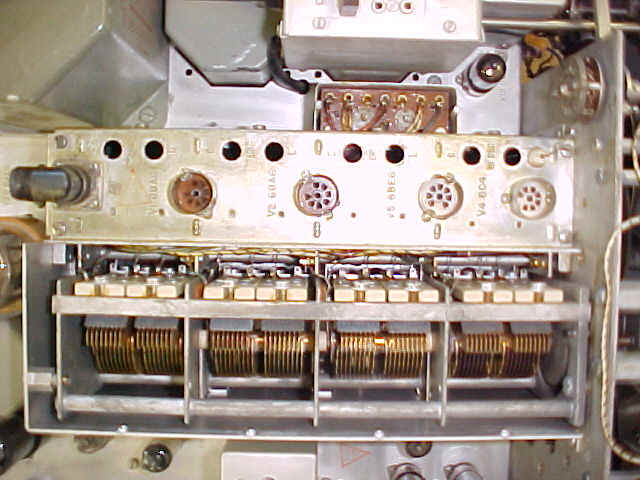
(1) RF Deck (Fig 3)
(2) T1 Pod (Fig 3),
(3) IF transformers (Fig 3),
(4) Band switch turret coils (Fig 4)
(5) T9 (HFO oscillator section) (Fig 4),
(6) Xtal Frequency Control Unit (Not on plain J models) (Fig 3),
(7) Underchassis (fig 4)
A. First Steps: This should be the removal of the Xtal Frequency Control Unit (FCU) (this assumes you have an SP-600 with the XFCU) as this makes access to the RF deck and especially the T1 pod is much simpler. Refer to figure 3. Removal of the right side panel makes access to T-1 much easier.
1. Remove the Xtal selection knob and shaft by loosening the various couplers attached
to the shaft between the front panel and the FCU and slide it out through the front panel.2. Loosen the coupler on the Delta Freq control shaft and slid it towards the FCU so the coupler is completely on the long shaft from the FCU.
3. Remove the bracket from the bottom of the FCU that goes to the long spacer near the power transformer. One end is held by a nut at the power transformer. The other end of the bracket is slotted and just slides into a groove on one of the supports for the FCU, so there is nothing to loosen on that end.
4. Unsolder the cap that comes from the FCU to the switch on the front panel.
5. Flip the radio over; locate where the wire harness from the FCU passes through the chassis. Unsolder the wires from their respective terminals. Make notes and keep track of where they attached -- they are color-coded.
6. Remove the four screws that secure the Power Supply filter assembly to its set of spacers and carefully lower the filter assembly, there is no need to unsolder anything here, just support it carefully.
7. With the filter out of the way you can get to the four screws that secure the spacers for the FCU, remove these screws while supporting the FCU so it doesn't fall.
8. Reposition the PS filter assembly and put back in a couple screws to temporarily hold it in place.
9. Flip the radio back over and carefully lift the FCU out, be careful of the long shaft so it doesn't bend and damage the Delta Freq capacitor when removing the FCU.
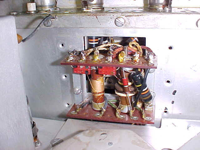
10. Remove the twelve screws from the FCU cover and open it up. There are two BBODs that need replacing in here. Reassemble the FCU and set it aside, don't reinstall yet!
FCU
B. RF deck - refer to figure 3
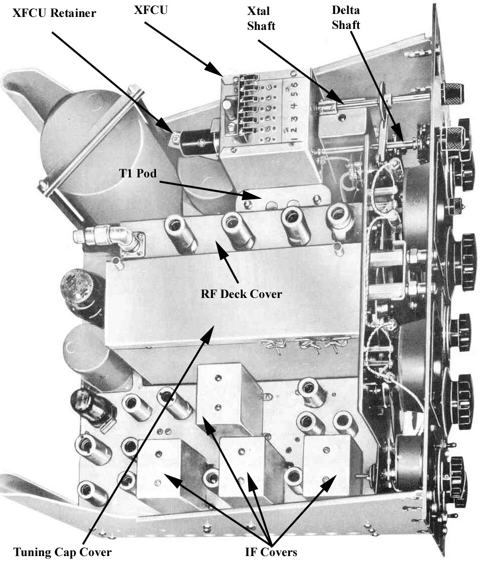
1. First remove the cover over the tuning caps (9 screws), then remove the screws (8) from the RF deck itself.
2. Remove the cover from the T1 pod (two nuts)
3. Unsolder the wires from the RF deck to the T1 pod (6 wires); keep
track of them by the color code. 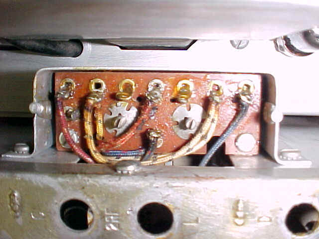
4. Unsolder the wires from the RF deck to each tuning capacitor (total of 12 wires, three for each tuner cap section)
5. Unsolder the ground straps from each tuner cap to the RF deck (4 straps)
6. Remove the cover over the bandswitch turret assembly underneath the chassis.
7. IMPORTANT!!! Before removing the RF deck, do one of the following:
Option A. Position the band switch 1/2 way between bands so no band switch coils are engaged in the fingers of the RF deck. I found this a little hard to gauge.
Option B. Completely remove a set of coils for one band, then turn the band switch to this position.
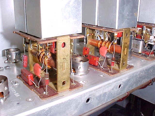
Since you'll have to take a set of coils out anyway to replace some BBODs, I chose this option, removing the entire set of coils for the .54 to 1.35 band, then turning the band switch to select this band. When removing a coil, be careful you don’t put stress on the ceramic and crack it. The retainer clips come out pretty easily, and will go back about as easy as long as you’re careful. Use of a curved hemostat or rt. angle small needle-nose pliers to grab them is helpful.
8. Once the band switch is positioned so no coils are engaging the RF deck fingers, you
can carefully remove the RF deck by pulling upwards. BE CAREFUL as it's a tight fit and you don't want to damage the ceramic plates for the fingers at each end of the RF deck.9. After the RF deck is out, you can replace the BBODs. They are obvious. There were a total of 22 on my RF deck, all .01mfds. It would be advisable to check all resistors in the RF deck, leaky BBOD's will cause many of them to overheat and increase in value. Now's the time to replace any that are more than about 10% from nominal value.
10. When all the BBODs are replaced, double check your work, you don't want to have to remove that deck again to repair a cold solder joint or short!
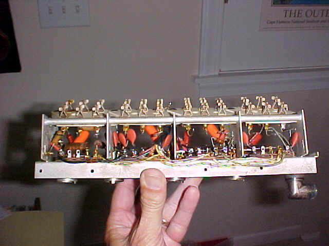
RF Deck before
RF Deck
after
11. Set the RF deck aside for the moment.
C. T1 Pod - Refer to figure 3.
1. The top cover should already be off. Complete the disassembly by removing the side cover (6 screws). This is why we left the FCU out, these screws are pretty difficult to get to with the FCU installed.
2. There is only one BBOD to replace in the T1 pod.
3. Reassemble the T1 pod side cover.
D. RF deck, FCU and side panel re-installation - Refer to figure 3.
1. Carefully re-install the RF deck. Watch the ceramic plates. Resolder each of the 12 wires to the tuning caps, resolder the tuning cap ground straps and resolder the wires to the T1 pod.
2. Once the RF deck and T1 pod cover is reinstalled and secure, re-install the FCU using the reverse procedure of the removal instructions. Be careful not to damage the protruding shafts. Replace the side panel if it was removed.
E. Checkpoint
When everything is back together, you may want to make a test to see how it's working. This is assuming you had already done a resistance and power check originally and were satisfied as to its previous operating condition. This test will at least see if there has been any improvement or if something has now gone completely dead. Make sure you aren't testing on the band that you removed the turret coils from. You don’t need to re-insert the coils for the band you removed just yet.
F. Turret Coils - Refer to figure 4.
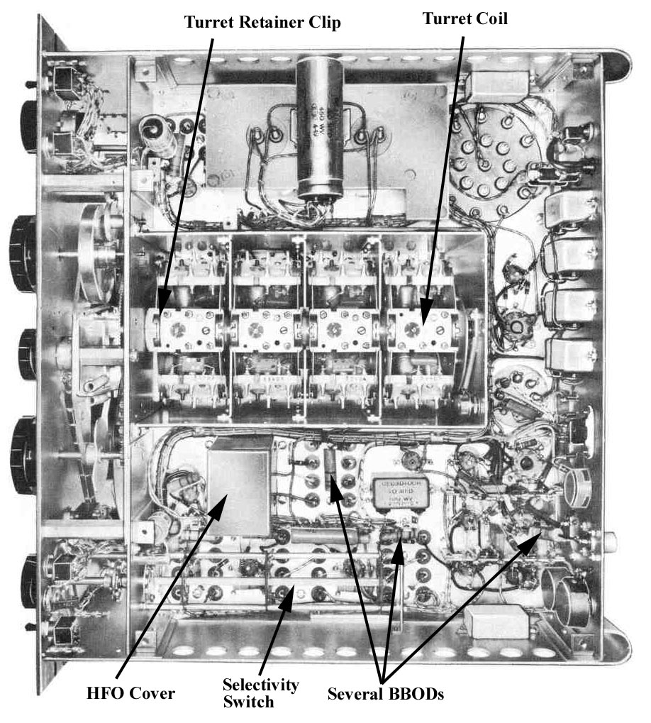
1. As long as you have one set out (if you chose to use this method) you may as well replace the BBODs on these now. They are easy to see as you rotate the band switch so you only need to remove the coils that contain the BBODs, there are 6 coils, three at the .54-1.35 band switch position and 3 at the 1.35-3.45 band switch position. The coils for the other bands, at least in my radio, did not use BBODs.
2. After replacing the BBODs and reinstalling the coils you may want to run another test to see what progress is being made.
G. IF Transformers - Refer to figure 3, and below.
Again, removal of the left side panel makes access to the IF cans and under the selectivity switch much easier. 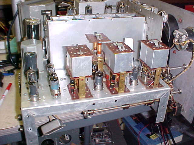
1. These are easy to do as the covers come off quite nicely and once off, with the tubes out, it's easy to get to the caps. It's not necessary to remove the cover for the Crystal (T3) IF unit as it turns out, on my radio at least, the BBODs were on the terminals on the bottom of the chassis, not in the IF can itself.
2. Again, after replacing the caps you can run another test to see that at least nothing has degraded.
3. Once satisfied, recover the IF transformer assemblies. Make sure the ground straps are still on top of the adjustment posts.
H. T9 HFO assembly – Refer to figure 4.
1. This is under a metal shield next to the selectivity switch assembly. You'll need to remove the four screws and lift the shield off, be careful of the phenolic locator board inside the shield, it's used to keep the circuit board upright so it doesn't vibrate and short out against the shield. Make sure it's installed correctly during reassembly.
2. Replace the BBODs (one of these was in a pretty awkward place, probably one of the hardest to replace).
3. Test the radio, then set the phenolic board and reassemble the cover.
I. Underchassis - Refer to figure 4.
This is the final step and relatively straight forward as it's easy to spot all the BBODs.
The ones under the selectivity switch were the most difficult to replace, however I found the following to be quite helpful. Unfasten the selectivity switch from the front panel and the rear bracket of the switch from the chassis. This allows the switch to be moved around somewhat based on the flexibility of the wires attached to the switch. This provided me with enough room to get under the switch and swap out the BBODs. Just be careful not to flex the switch assembly too much and break a wire, or worse, a switch wafer. That much stress shouldn't be needed as you only need a few tenths of an inch more clearance to get to the BBODs. You may find it easier if the side panel is removed.
Well, that's the summary. I'm sure I left out some little, but obvious steps, the idea is just to show how the job could be broken down into manageable steps. Once I had completed the ground work of tracing out the schematic and identifying the locations on the figures I spent two evenings performing this operation. One evening to do the FCU/RF deck and T1 pod, and the second evening doing the remainder. In conjunction with this I was having several conversations with chaps on 29.0mc AM as the band has been open evenings quite a bit. So figure two pleasant evenings for this, you could probably do it in one evening if you didn't spend time trying to ham it up as well!
As for the results: After the recapping was complete, I fired up the receiver and, without doing any form of alignment or having the need to perform any troubleshooting other than the one original bad resistance check, the radio went from virtually very weak audio and picking up only distorted AM signals from a couple local AM broadcast stations to a completely functioning and beautiful sounding radio. It's amazing what just replacing those caps does. The dial accuracy is fantastic, I dialed up both 10.0mc and 15.0mc and WWV was right there.
Eventually I did perform an alignment but it made very little improvement over what was accomplished by the simple task of performing this recap. Believe me, the two evenings spent replacing everything was far, far better time spent than trying to troubleshoot problems one by one in an attempt to avoid replacing a cap or two that might not need it.
Hope someone finds this useful and if anyone has any additional suggestion, tips or corrections, hop in!
·
I recommend that you have a copy of an SP-600 manual when attempting these changes.·
I made good use of the wealth of material available from the BAMA ftp site ftp://bama.sbc.edu/ and the R-390/SP-600 CD-Rom from Jeff Adams jadams@mcqassociates.com. Both contain very good photographs of the chassis with parts clearly labeled which you’ll find useful in identifying the location of the various components mentioned in the following cross reference.BBOD Replacement Capacitor Cross-Reference list for the SP-600
C = used as Coupling cap, B = used as Bypass cap
.
01 mfd capsSymbol Location
.022 mfd caps ( can use .01mfd as well)
Symbol Location
Fig. 5
|
![]()
![]()
![]()
![]()
![]()
![]()

